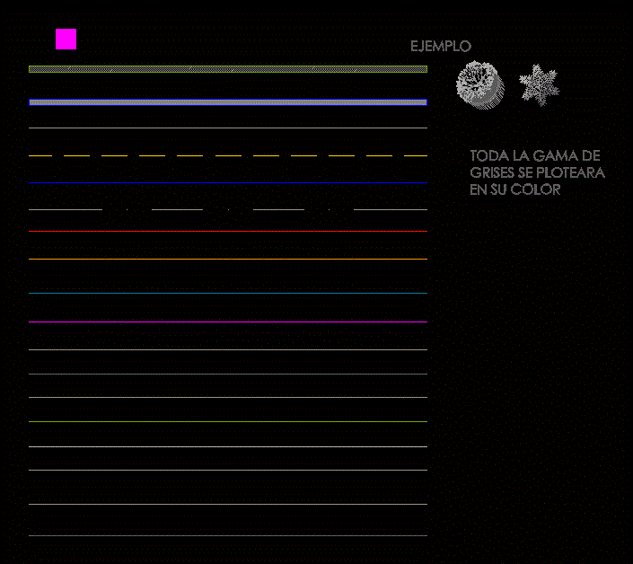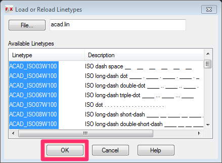
Now the ElectroMag line type exists in this drawing. 36 then ENTER, or select the end point of our shape select our shape then ENTER. A linetype definition must exist in a LIN library file before a linetype can be loaded into a drawing. To use a linetype you must first load it into your drawing. A complex linetype is a repeating pattern of symbols. Type MKLTYPE then ENTER save this file to the same location as the shape file with the same name " ElectroMagnetic" back in AutoCAD type ElectroMagnetic then ENTER for the name leave the description blank and then ENTER type 0,0 then ENTER for the starting point drag the cursor to the right and either type. A linetype is a repeating pattern of dashes, dots, and blank spaces. Now that the shape file is inserted we can create a line type. Type SHAPE then ENTER type the shape name which is ElectroMagnetic then ENTER type 0,0 then ENTER for base point then hit ENTER which leaves the scale at 1.0000 type 0 then ENTER for the rotation angle. For example, the Continuous Linetype appears like a solid. It is also used in layers, where we can define different LineTypes for different layers. We can adjust the line width and Linetype according to the requirements.

Type the command MKSHAPE then ENTER find an easy place to locate this shape file like the desktop and save it as ElectroMagnetic.shp back in AutoCAD type ElectroMagnetic for the name then ENTER Since this shape file has curves type 512 for the resolution then ENTER type 0,0 then ENTER for base point select both of the created polylines then ENTER. Linetype in AutoCAD is defined as the pattern of symbols, dots, text, dashes, continuous lines, etc. This lin file will contain all custom linetypes of your current drawing.ĭo you have questions related to this tip? Let me know in the comments below.Now you need to turn this into a shape file. Now type LINOUT on the command line and press enter, a new linetypes.lin file will be added to the same folder in which your current drawing is stored. When the file is loaded Click on the close button. This will open Load/Unload Applications window, locate the file location from Look In dropdown menu select LinOut.vlx file and click on load button.

Once you have that file type APPLOAD on the command line and press enter. A linetypes in AutoCAD has just one color, assigned either directly (thru the Color command) or by the layer. If you have a drawing containing completely new linetype and you don’t have its linetype file then there is a VLX file courtesy of that can make exporting linetype from your drawing a seamless task.ĭownload the LinOut.vlx here, File courtesy of Next is the length of the smaller dash (.25). Next is the location of smaller dash from the left side of the longer dash (-.25). AutoCAD linetypes must start with a dash. Next is the length of the first dash (1.25). The definition always begins with a capitol A. Exporting custom linetype from the drawing: The bottom line is the linetype definition. When you transfer your drawing containing this custom linetype then also make sure to transfer linetype and shape file created in examples above with it.

If you find that scale of this line type is not appropriate then you can change its scale by changing LTSCALE system variable to appropriate value or by changing the scale of individual objects from properties palette.

You can now apply this linetype to geometries in your drawing. The linetype is now created with name TESTLT and it will also be loaded in the drawing.


 0 kommentar(er)
